Consistently Delivering Machining Excellence
Trace-A-Matic uses state-of-the-art, fully automated CMMs (Coordinate Measuring Machines) and powerful PC-DMIS (Personal Computer - Dimensional Measuring Interface Standard) software. To measure and verify critical external and internal part dimensions, complex geometry, overall machine tool output, and other vital features as specified. An outside IEC 17025 accredited calibration facility oversees our rigorous calibration system. All of our facilities are climate controlled at 70°F ±2° with relative humidity below 40% to ensure a stable testing and manufacturing environment.
For the highest quality parts, made to print, the first time, Trace-A-Matic is your world-class precision machine shop!
Inspection Capabilities Summary
Part Size:
Bridge CMM Capacity of 79” x 130” x 59” at 14,300 lbs.
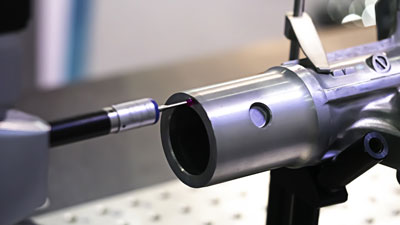
- Deep Feature Probing - CW43L wrist offers infinite rotation and probing depths to 38.9”
- Full Contact Analog Scanning - Utilizing Renishaw SP25M probe system
- Exceptional Accuracy - ISO10360 accuracy statement is 5.5+L/286 MPEe
- CMM inspection is available at our Brookfield, WI, and Houston, TX locations
Machined Feature Inspection:
External and internal dimensions, external and internal geometry, boring, counterboring, countersinking, drilling, facing, gear hobbing, internal forming, knurling, milling, necking, parting, pocketing, profiling, reaming, shoulder facing, spline, tapping, threading (external, internal), turning (contour, form, taper, straight), thread milling, surface finishing, and other features as specified
Equipment Brands:
Hexagon - Please refer to our Equipment List for CMM information and capabilities.
Coordinate Measuring Machine CMM Overview
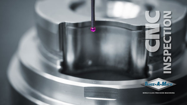
A process engineer or quality lab technician generates CMM programming to read and verify critical component markers established by our engineering evaluation process. Machined parts or assemblies rest upon or are affixed to the stationary granite measurement table, or held in place by use of a fixture. The CMM probe travels on the Z, Y, and X-axis precisely interacting with the part as the PC-DMIS programming dictates, recording every marker and bringing alert if an issue is present. Machining parameter adjustments quickly result when observing variation in the machining process. The CMM testing process gathers a wide range of precise measurements and verifies even the most complicated part geometry.
CMM Anatomy
- Probe - The instrument that travels on the Z, X, and Y-axis that comes in physical contact with the part
- Vertical Ram - Holds the probe and moves on the Z-axis (up and down)
- Component - The machined part or assembly the CMM machine is measuring
- Granite Measurement Table - An extremely heavy-duty, stationary bed that holds parts and fixtures for inspection
- Bridge - Allows the probe and ram to travel on the Y-axis (left and right)
- Carriage - Travels the length of the granite measurement table on the X-axis (front and back), transporting the bridge, vertical slide, ram, and probe
- Pendant/Jogbox - The interface a quality technician uses to manually program and control how a CMM operates

CMM Inspection Photo Gallery

Complex Geometry Inspection
Dimension Verification

In-Process Testing

CMM Part Fixturing
CMM Inspection Video


Other CNC machining services offered: 5-Axis Machining, 5-Axis CNC Machining, Multi-Axis Machining, 4-Axis Machining, 3-Axis Machining, Horizontal Milling, Vertical Milling, Horizontal Turning, Vertical Turning, CNC Engineering, CNC Inspection, and Special Machining Process
All product names, trademarks, and registered trademarks are the property of their respective owners.